Tempest Restoration
Wondering if you've got anything fun hiding in your garage that needs some work that you might willing to part with. - Me
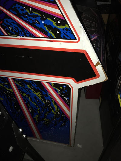
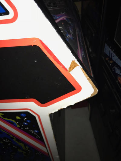
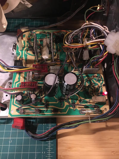
I bought the Tempest cab from a friend of a friend Justin R. It was my second machine. The first, an Asteroids Deluxe, I had also bought from Justin a few months earlier. I felt as though it was important to start looking for another project soon after having finished the Asteroids restore. I wanted an opportunity to test what I had learned the first time through, to attempt to do it with as little help as possible. My ideal cabinet is one that is fun, broken in some way, and in reasonably good cosmetic condition: the side art is intact, the control panel overlay isn't worn through or covered in cigarette burns, the marque is clean. Machines in this condition have two important characteristics; they are affordable and they're fun to fix! Turns out that Justin had an old Tempest in the back of his garage that he'd planned on fixing but hadn't gotten around to. When he bought it the game started up but the monitor wasn't working (playing blind), he sent me the following pictures:
Tempest was released by Atari in 1981 (the same year as Asteroids Deluxe!), it was the first of a handful of color vector games released from '81 to '85. It's an awesome, frantic, colorful, and completely unique game. It's is one of the greatest of all time arcade games, and Justin is willing to sell it to me for a reasonable price. So what's a man to do but drive down to a tiny little rural town outside of Tacoma. To a suburban home with a two car garage filled end to end with Arcade and pinball machines. To take home a beautiful broken old game from 1981.
Atari machines of this era were all composed of roughly similar components. Power Supply: Transforms 120vAC into a bunch of different voltages, supplying the boards, sound, marquee, monitor among others.
Audio Regulator Board: Isolates and amplifies audio from the board.

Main Board: The computing system that the game runs in. A big PCB that houses a CPU, ROM and Ram chips, and accessory processing.
Control Panel: A bunch of buttons and lights and UI for the player. Monitor: A CRT that displays the game. Harness: A maze of wires that connect all the components together.
One fun thing is that these machines were built with the assumption that operators would be required to maintain and repair them. Subsequently they came with an astonishing amount of high quality documentation. One of the first and most important steps to take when beginning a repair is the familiarize yourself with the machine and documentation.

These manuals are filled with schematics, debugging procedures, parts lists, they're amazing.Once the machine is home I begin a process of general diagnostics. Many individual parts: capacitors, transistors, resistors, integrated circuits; that make up these games can fail with time and use. I clean and check all the components in the cabinet then begin testing each one starting from power and moving towards the monitor.
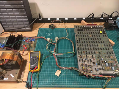
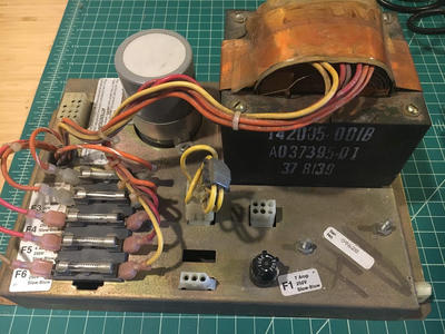
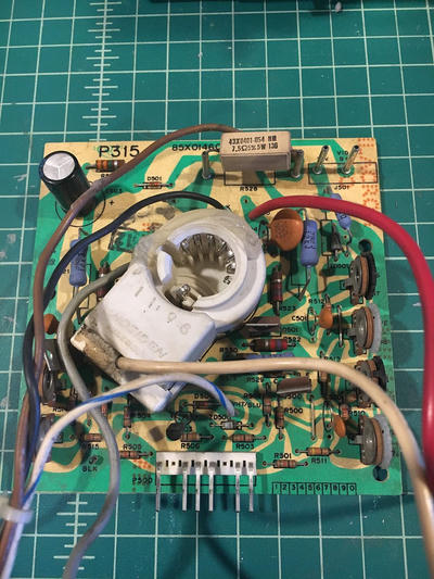
When I got everything out on my bench and started testing I only found a minor issue on the AR board (the 12v DC line was dead indicating a dead 7812 voltage regulator). Testing the +12VDC I was only reading 1.2VDC tracing back from the text lug the next component back is the 7812 Voltage regulator, but the voltage leading in was correct (22VDC). This indicates a failure of that part, I've removed it and ordered a new replacement for the next round of testing.
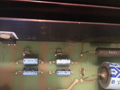
Here it is after the fact, you can see the +12VDC test lug used.So I connected all the components together and flipped the switch. Unfortunately out on the bench the game wasn't playing blind. After some double checking of my intuition and that I was getting appropriate voltages on the board I was convinced that the game wasn't running.
Debugging a board like this is debugging a computer, to debug it we have to understand how it's supposed to work. Once again we are lucky and many of the functionings of this computer were meticulously documented by Atari. Like with debugging the power the best place to start with debugging the main board is at the beginning. The game runs off of a MOS 6502A CPU whose clock is driven by a simple circuit called the "clock circuit".
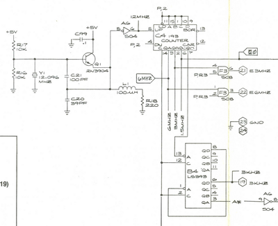
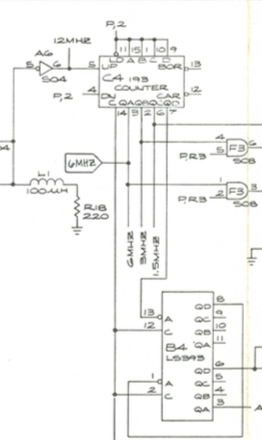
Without the clock signal the CPU will be effectively dead, so our first job is to ensure this circuit is operating correctly. We can do this by using a logic probe this cheap tool lets us observe the state of the signals running through out the board and has some crude measures of the rate of signal changes. The clock circuit works by taking outputs from an oscillating crystal and feeding them to a "counter" IC. This circuit in turn has the effect of splitting that signal into a number of separate frequencies (it turns out that the "counting" functionality of this IC isn't used at all). The new frequencies are then passed onto a handful of other circuits including the CPU.
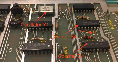
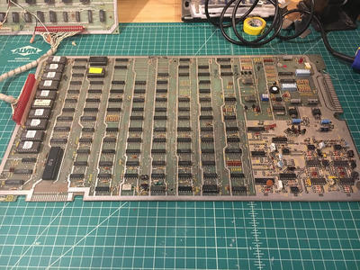
In the above picture we can see the clock circuit, notice the oscillator as well as the C4 and B4 counters. As a brief note it's worth describing how Atari labeled parts on their boards. All the ICs are in a grid with rows labeled A to Z and columns 1 to N. So when describing a chip as C4 we are looking in the C row at column 4. As an example the chip to the left of C4 picture would be labeled C5. As a further note all the ICs are in what are called DIP packages (dual in-line package) whose pins are labeled from pin 1 counterclockwise to pin N.
In the case of the Tempest I was working on I could trace a correct signal from the crystal to pin 5 on the Counter C4, but there were none of the output signals that should have been seen on pins 14,3,2,6, and 7. It isn't uncommon for the ICs on these boards to fail over time and that appears to be the case with this one. Surprisingly this was also an error that I found on my Atari Deluxe, perhaps these 193 chips are starting to fail. So we come to the end of our first story with a bad SN74193N counter (the datasheet on this is also amazing and fascinating and worth reading to see how it works). When the new chip arrives I'll remove the old one, replace it with a 14 pin socket, put a new chip in its place, and we'll hunt for the next bug.
Repairing the Clock Circuit
C4 (an LS193 counter) was getting a clock signal from the oscillator but no outputs were observed. With some pattern matching since the LS193 chip was bad on my Asteroids Deluxe I immediately jumped to that as the cause this time. However, when I replaced this chip the results were exactly the same "ohno". After spending a lot of time looking at this diagram and reading the datasheet I eventually realized there is one more input to C4. You can see it labeled "C" in the diagram above. This pin (C4–14) is the "clear" pin, it resets the chip when it's held high. When tested with a logic probe, this pin was always high. This is incorrect behavior of the board and will cause the chip to never properly begin operations. With that knowledge in hand I followed the lead.
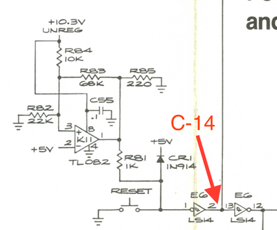
The next circuit back is the "Power and Reset Circuit" which is responsible for managing the incoming 5v and 10.3v rails and reseting the board via a reset switch. The two circuits are connected between C4–14 (our stuck high pin) and E6–2. E6 is an inverter, inverters take a signal either low or high and flip it. When tested the E6 chip appears to be working, E6–2 is high because the input E6–1 is low, but E6–1 should not be low.
The expected behavior of this circuit is that 5v runs to E6–1 (high) which is flipped to low to run to the clear pins in the clock circuit, E6–1 is pulled to ground via the reset switch, which resets the clock chips by bringing those pins high. If E6–1 is always low then something is very wrong. I have to admit that I don't fully understand what this circuit does. Talking with my friend he thinks perhaps it's responsible for creating a quick pulse that issues the initiating clear signal that starts all the chips. Either way, once again we move back through the circuit. The reset button tested correctly (it wasn't stuck open), the +5v line is correctly supplying +5v, but one further step back the +10.3v supply was completely missing!
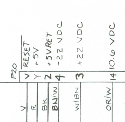
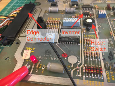
All inputs to the board come through an "edge connector" a 44 pin connector that grips onto a bunch of fingers on the board (this looks a lot like the edge connector of a game cartridge like an NES game). It's a reasonable place to look to find where power comes in. The pin out for this connector is well documented and lists +10.6v as an input (unclear why there is that .3v discrepancy but let's just ignore it). I could test connectivity between pin 14 and R84 in our reset circuit so what was going on?! Well the joke is on me because I can tell you, I chased that orange and white (OR/W) wire back through the harness and what did I find? Oh … a connector that wasn't connected. This really simply runs a direct line from 10.3v off the power supply to the edge connector. This was not a connector that existed on the Asteroids Deluxe and I guess I just missed it. I plugged the two connectors together and the board immediately booted correctly.
Repairing the Monitor
With the board now booting we are able to put everything back in the cabinet and focus on getting the monitor working. You might say "How do you know the monitor doesn't work without testing it?!" and I would say "Because it came to me in a pile of pieces!", so at the very least I'll need to put it back together. The monitor in a Tempest is a Wells Gardner 19K6100. It's made up of four main components:
Deflection board: Amplifies input signals from the board. Since this is a vector monitor there are five signals X, Y which control the electron gun's position in the 2D plane and RGB which define what color it should be.
In this picture the board is actually powered on! You can see the "spot killer" LED is on.High Voltage Board: Cranks up the voltage needed to sustain the flow of electrons from the cathode towards the anode and on towards the screen.
![]() The big black thing is the HV transformer or "flyback".Neck Board: Modulates input signals from the Deflection Board to move the electron beam.
The big black thing is the HV transformer or "flyback".Neck Board: Modulates input signals from the Deflection Board to move the electron beam.
 The weird alien mouth thing connects directly to the back of the tube.Tube: A big glass vacuum tube, the screen face is coated on the back with phosphor that's excited by the electrons smashing into it and makes it glow.
When debugging these old monitors the first thing to do is to get all the parts out and inspect them. It's very common for wires to break, for the solder on jumper pins to crack, and for a number of other components to fail. It's best to start with the easy stuff. This monitor was slightly complicated because it was sold to me mid repair and so the state of things was slightly more difficult to figure out and so I proceeded cautiously.
The first thing I did after all the boards were out, cleaned off, pins reflowed, and wires reattached, fuses replaced, was to check the power transistors on the chassis. These transistors (sometimes called "bottle cap" transistors because of their similarity) are frequent failures and so it's a good idea to check all of them. In this case of the 6 transistors I found 5 to be faulty.
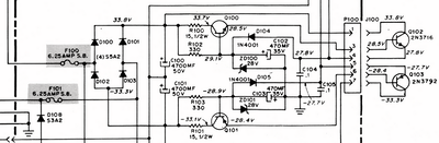
I was worried about the low voltage (LV) circuit on the board because two fuses (F100 and F200) were blow. Those fuses sit at the beginning of the LV circuit and protect against excess voltage coming from 25VAC lines. In fact, this part of the deflection board is so prone to failure that there's a complete off the shelf replacement you can purchase! But, I tested all the components and everything seemed okay, so I moved forward. At this point I tried powering on just deflection board with no other components connected and tested the low voltage lines. I got a solid 4.8v and so I moved onto the neck board.
I did have a funny scare in all of this when I plugged the transistors into the board and the spot killer LED turned on and I jumped, thinking for a moment that I was working on a live board. It was just the big capacitors on the board draining though and I was relieved. The neck board was in a bit of rough shape. A number of wires had broken, and the connection from the high voltage board looked fried. But the neck board is the simplest of the boards and so I resoldered the wires and cleaned it all up.
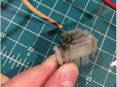
Here's that fried connector. I didn't have a replacement so I just put new pins (0.084" molex female) on the wires and skipped the connector.With the neck board done, I connected the deflection board to it, and the deflection board to the main board, turned the power on… and listened. When the neck is getting proper signals from the deflection board it will make a sound called "chatter" which sounds a bit like rhythmic static. Immediately the neck powered up and chattered about. You can even hear the change in what's being rendered as the chatter changes frequency.
Last but not least I needed to get the high voltage board up and running. Three things stood out on this board. First, there was a transistor on it that had failed, second was an oddly replaced 3.9ohm resistor that had been piggy backed onto another resistor, and finally there was a diode shorted to a wire with a solder bridge.
{{ resize_image(path="./blog/tempest-restore/monitor-components-in-board.png, width=400, height=640, op="fit") }}
That yellowing plastic disk thing at the bottom will come back up in a second.I fixed those up, and plugged the HV board into the neck and deflection boards. I wanted to test what the output of the HV lines would be before plugging everything into the main board or running stuff for any amount of time. To this you can slide a special high voltage probe under the anode cap (the suction cup in this picture). The probe is great for discharging CRTs nicely but it also acts as probes to your multimeter with a 1000:1 voltage reduction.
{{ resize_image(path="./blog/tempest-restore/monitor-measuring-high-voltage.jpg, width=400, height=640, op="fit") }}
The HV line should measure about 20kV, but after a great deal of hemming and hawing and sweating before turning this all on, I was only measuring C4 (an LS193 counter) was getting a clock signal from the oscillator but no outputs were observed. With some pattern matching since the LS193 chip was bad on my Asteroids Deluxe I immediately jumped to that as the cause this time. However, when I replaced this chip the results were exactly the same "ohno". After spending a lot of time looking at this diagram and reading the datasheet I eventually realized there is one more input to C4. You can see it labeled "C" in the diagram above. This pin (C4–14) is the "clear" pin, it resets the chip when it's held high. When tested with a logic probe, this pin was always high. This is incorrect behavior of the board and will cause the chip to never properly begin operations. With that knowledge in hand I followed the lead. The next circuit back is the "Power and Reset Circuit" which is responsible for managing the incoming 5v and 10.3v rails and reseting the board via a reset switch. The two circuits are connected between C4–14 (our stuck high pin) and E6–2. E6 is an inverter, inverters take a signal either low or high and flip it. When tested the E6 chip appears to be working, E6–2 is high because the input E6–1 is low, but E6–1 should not be low. The expected behavior of this circuit is that 5v runs to E6–1 (high) which is flipped to low to run to the clear pins in the clock circuit, E6–1 is pulled to ground via the reset switch, which resets the clock chips by bringing those pins high. If E6–1 is always low then something is very wrong. I have to admit that I don't fully understand what this circuit does. Talking with my friend he thinks perhaps it's responsible for creating a quick pulse that issues the initiating clear signal that starts all the chips. Either way, once again we move back through the circuit. The reset button tested correctly (it wasn't stuck open), the +5v line is correctly supplying +5v, but one further step back the +10.3v supply was completely missing! All inputs to the board come through an "edge connector" a 44 pin connector that grips onto a bunch of fingers on the board (this looks a lot like the edge connector of a game cartridge like an NES game). It's a reasonable place to look to find where power comes in. The pin out for this connector is well documented and lists +10.6v as an input (unclear why there is that .3v discrepancy but let's just ignore it). I could test connectivity between pin 14 and R84 in our reset circuit so what was going on?! Well the joke is on me because I can tell you, I chased that orange and white (OR/W) wire back through the harness and what did I find? Oh … a connector that wasn't connected. This really simply runs a direct line from 10.3v off the power supply to the edge connector. This was not a connector that existed on the Asteroids Deluxe and I guess I just missed it. I plugged the two connectors together and the board immediately booted correctly. about 10kV, half of what I needed. There are adjustment pots on the HV board to easily fix this, but you want to be a little careful since if it's not even close to in range it might mean something else on the board is failing and you're just gonna fry it. Also the revision of the HV board I have (P329) has a special circuit to turn off the HV line if the voltage gets too high. That circuit was added later in the monitors life time to reduce change of X-Ray exposure. If that goes off I'll read 0V, so we aren't there yet. So I tried adjusting it (with some caution), moving it high and I got 10kV, moving it low and I got 10kV. The thing to know about these potentiometers (pots) is that they break and corrode and otherwise fail frequently. Broken I thought. Pulling out a multimeter with a lead on each side you can easily test if the potentiometer works by checking if the resistance changes. This one was stick at 12.93 ohms. Broken. I sat for a bit and figured I'd try rubbing the pot back and forth a bit. The way these things work is there's generally a sliding lead in the dial that touches some bit of metal on the other side (lots of times it's a loop of material) such that the further along you go the more resistance there is. It's not uncommon for corrosion to make it so that a good connection never forms and you can sometimes get them working again by just rubbing them a bit. So, I gave it a few full turns, and the dial came off. Broken.
High Voltage Board
Unfortunately the failed pot turned out to be a red herring. The pot was broken, but when I replaced it HV output was still pegged at 10kV. The WG6100 FAQ / Guide has a section that sounds really familiar. I have seen several HV boards where ZD902 (150 volt Zener diode) goes bad and the HV drops from 19.5 kilovolts to around 10 kV. Based on their list of suspected parts I replaced the components circled below.
{{ resize_image(path="./blog/tempest-restore/high-voltage-schematic.jpg, width=400, height=640, op="fit") }}
All three of the transistors Q900, Q901, and Q902 all tested bad when pulled, and Zener Diodes (ZD902) can't be tested with a digital multimeter so I just replaced that blindly. At this point I went back to testing the voltage and with a little adjustment I managed to get 19.75kV! This is pretty exciting since it's a big leap forward in terms of the function of the monitor, and it's encouraging that nothing else failed when I got it running. While we celebrate it's important to test the B+ voltage, this is the input voltage to the HV transformer and should read exactly 181v. The same pot that adjusts the HV adjusts the B+ but your B+ adjustments are more precise and tunable. It's also exciting because the sound and feeling of a fully running CRT is a different experience than a dead one. When you turn it on the sound of static immediately ripples across the front of the tube, this hum and crackle in a way that just speaks to danger in your hind lizard brain. Even though there isn't any appreciably difference in danger with the doubling of voltage everything feels a lot more dangerous and my adrenaline runs a bit higher now.
{{ resize_image(path="./blog/tempest-restore/high-voltage-vertical-collapse.jpg, width=400, height=640, op="fit") }}
With 20kV we'll start to see images on the screen, so it's time to attach the game board to the monitor and see what we get. Previously we had heard chatter when attaching the neck so I was hopeful that the whole thing would just spring to life at this point. Unfortunately what I actually got was this horizontal smear. Sometimes called "collapse" this often indicates an issue with the analog output of the main boar It's common for the pots one these old monitors to get old and corroded and fail (remember that HV pot we were working on?). You can sometimes get them to fee up a little just by rotating them back and forth, cleaning off old corrosion. I started with the pots on the monitor but nothing happened. But messing with all the pots on the main board the monitor suddenly snapped to life.
This is what happiness looks like
Finally with everything working it was time to put it all back in the cabinet and enjoy the game. I want to tell you it all worked out, but reality intrudes. I got everything back in the cabinet, wired it back up, flipped the switch and a quick little snap told me all I needed to know. The screen was dark again. I pulled the monitor back out onto the bench and my heart sunk as I measured B+ at 25v. Measuring HV I got nothing at all (this makes sense if you know that B+ feeds the high voltage transformer and 25v isn't anywhere near enough to make it work). It was as if I had done nothing for weeks, not only was the monitor back to dead, but there were so many possible ways to fail that I would functionally need to start again. So next time… I over.