Current Sensing With Large Currents
The current project I'm working on, a relay that provides remote triggering and voltage and current measurements back to the user, has been plodding along. I recently got the boards delivered and I've been working on assembly and as such I've been finding the mistakes you make in a V0 prototype.
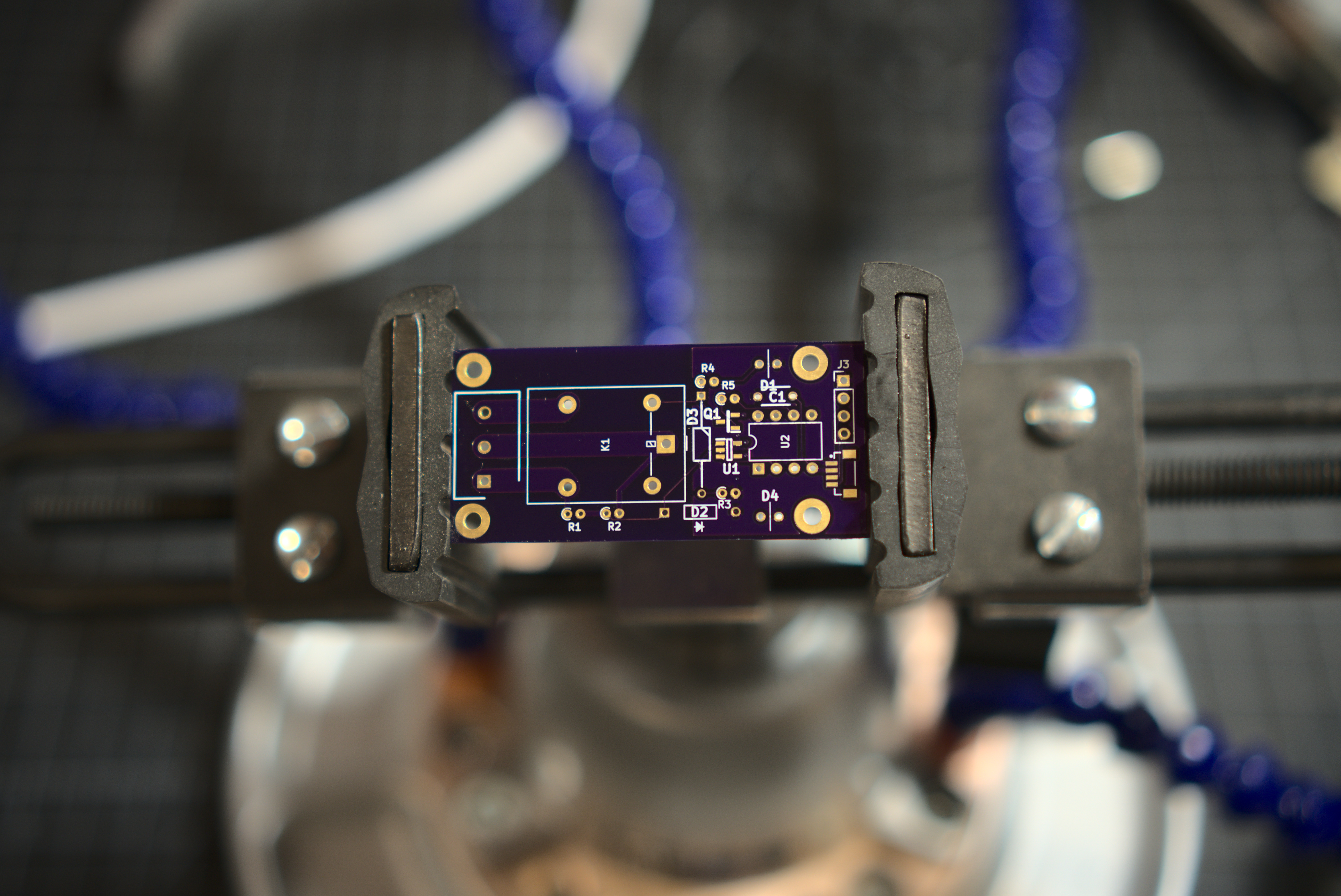
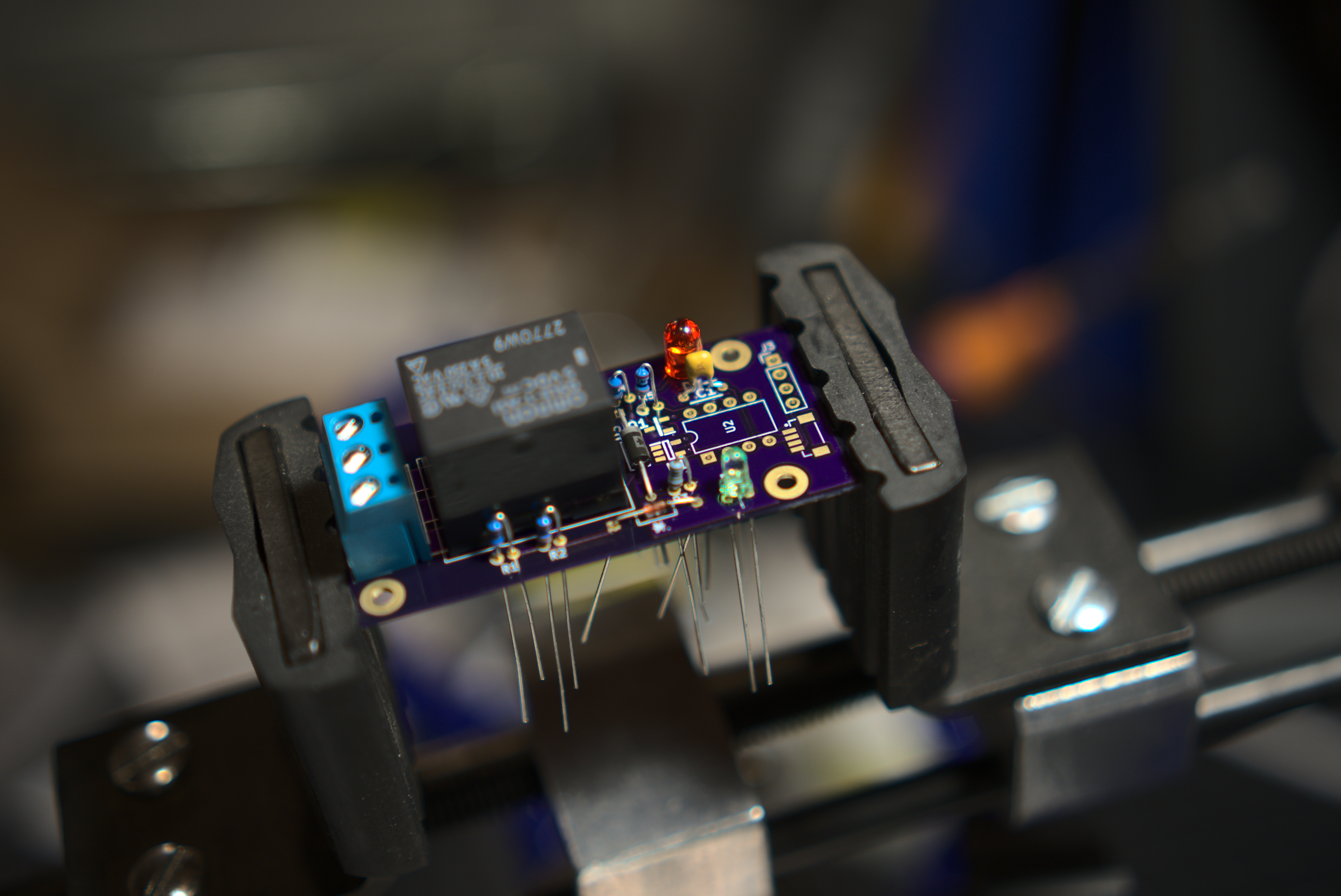
Here are some pictures of the boards as the arrived from the manufacturer and a dry fitting.
The biggest mistake is that I've radically missunderstood the way that the TI TMCS-1101 hall effect sensor works. My mental model of this device was that it operated in parallel with the existing current path, took some trickle current, measured that and amplified it. But that is NOT the correct model. As I was reading the datasheet again it became clear that this device is expected to run in series with the current path as shown in this picture. While that in and of itself wouldn't be dissasterous it made me think more about the overall design parameters of this project.
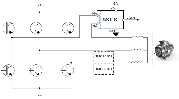
Ultimately I want to be able to drop one of these relays into a solar charging sytem that could supply loads as high as 100A with a voltage of 40v. In my previous mental model I wasn't worried too much about the total current load since I expected the device to be shunting the larger current, with this new model I think it's unlikely that I find a surface mount chip that can sustain 100A loads for long.
So, step one has been, digging deeper into the methods of current sensing. Digikey has a nice summary article on the topic. From there it seems like I should be thinking about a shunt resistor design, basically a low resistence, high watt, resistor that we can observe the the voltage differential across, since the voltage drop is proportional to the current (V = I/R) we can use that differential to measure the current through the resistor.
Small mistake... totally forgot a current limiting resistor on the power LED.
Another observation from reading more about current sensing technology is that a lot of folks use heft Lugs on the PCB and that's an interesting direction to go if I'm going to need to run the full load through the device.
Notes: