Daily Log 2020-11-21
Triggering a Relay
Relays are electrically controlled switches. Most relays use mechanical connectivity for switching as opposed to semiconduction like a transistor (this isn't strictly true as there are semiconductor relays that blur the lines). Most often relays are found in high voltage / high current applications where semiconductors would impractical, they trade off cheapness and resiliency for speed of switching. An electromagnetic relay consists of contacts, a solenoid (a bit of wire wrapped around a bit of iron), and an arm that moves to connect between the contacts. When a small current is run through the solenoid it magnetizes and moves the arm between contacts turning them on or off.
I've been working on a design for a simple relay that also offers voltage and current sensing across the terminals, enabling simple programming for applications like solar battery charge management. For my uses I want to minimize power use while maximizing the power that the relay can transmit. In that regard, one dimension to consider when evaluating relays is the coil voltage and current, as this will define the power draw of the relay. In my prototype I'm using a G5LE-1-ASI which is a single pole double throw (SPDT) relay, the coil voltage and current are given as 5 VDC and 79.4 mA respectively, resulting in a minimum draw of approximately 400 mW.
Another consideration is how to trigger the relay, while the ATtiny85 controller I'm using can easily supply the needed 5V, 80mA far exceeds the safe operating current of any of its available outputs. In order to meet those current needs we'll need to find a way to connect the relay's coil to the power supply and trigger it via an output pin on the controller. This is actually a great application of the Op Amp I was discussing yesterday, in that case we wanted a high impedance input to buffer a signal from the high voltage line to the low impedance sensing. In this case we want to buffer the low current input signal to the high current output signal.
It turns out that selecting an appropriate transistor is tricky:
- Transistor type: MOSFETs for their ability to transfer large loads
- channel type: N channel types are considered easier to work with and are more efficient
- Gate to Source voltage (Vgs): The voltage at which the device is in the fully on state (logic level is shorthand for 3-5v)
- Drain Current Continuous: The amount of current that can run through the drain continuously
Based on that I found a reasonably priced SMD mosfet with a Vgs of 4.5V and Drain Current of 200ma. This should be completely sufficient for my uses of triggering the relay. Note that for prototyping these SMD mosfets are a pain to work with, but I have some simple adapters that allow me to solder one of them into a board that fits the PID-6 package which should work for my uses.
Resources:
- https://www.espruino.com/mosfets
- https://circuitjournal.com/which-mosfet-should-you-use-with-arduino
Last but not least one needs to consider Inductive Kickback. Kickback is the result of opening a circuit that contains any inductor. As current drops in the inductor the inductor resists the dropping current with a resulting increase in voltage. For a short period of time this voltage can be much greater than the supplied voltage, enough to damage sensitive electronics connected to the inductor. In the case of a relay the coil operates as an inductor and triggering the relay opens and closes the circuit and our sensitive electronics is our microcontroller. To protect against the effect we can place a diode across the coil. The Diode opens a loop for the current to flow from the inductor back into itself preventing the huge spike in voltage.
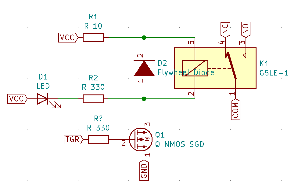
Below is a schematic view of a logic controllable relay:
Selecting resistors for LEDs
With Vf (forward voltage), Vcc (supplied voltage), Ifc (Forward Current), and our mystery R. Ohms law I = V / R
Ifc = (Vcc - Vf) / R R = (Vcc - Vf) / Ifc
As an example taking this LiteOn LED.
- Ifc: 30 mA
- Vf: 2.1V
- Vcc: 5V
R = (5V - 2.1V) / 30 ma R = 96.7 ohms
To save life and reduce brightness we know we can choose any resistor greater than 100 ohms and feel good.