Daily Log 2020-11-20
Operational Amplifier
The operational amplifier (Op Amp) is a common differential amplifier used in numerous devices around your house and around the world. It was first developed in 1941 and saw wide use but saw massive popularity with the invention of the MOSFET in 1959.
The standard Op Amp has two inputs, one output, and positive and negative supply. In the open loop configuration the Op Amp has limited practicality, with any difference between it supplies saturating one of the supply voltages to the output. This configuration is unstable with differences in supply voltage, temperature, and other conditions resulting in changes to the output. More common is to see op amps in closed loop configurations that feedback the output into the inputs.
The Relay project that I'm working on requires stepping down a large input voltage (0-50V) to a voltage that can be read by the Analog to Digital Converter (ADC) on an ATtiny85. In yesterday's log I outlined the challenges this provides given the constraints of low power consumption and low input impedance. With a naive voltage divider in order to meet the input impedance requirements of the ADC you would end up wasting enormous power through the voltage divider. The op amp provides a useful buffer. In a simple negative feedback configuration it acts as a 1:1 amplifier, taking advantage of the high impedance inputs and the low impedance outputs to separate the two electrical components.
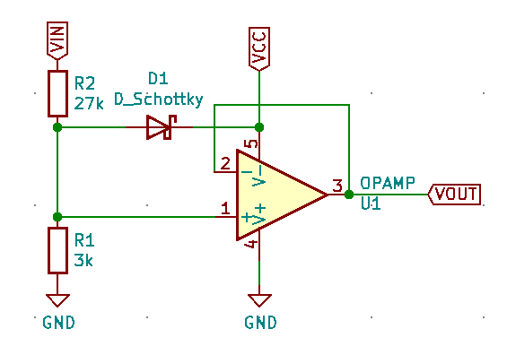
My question at the end of the day was "How does this actually work?". I could find a lot of resources explaining that in the negative feedback configuration the op amp's output will adjust to ensure there difference between + and - inputs is zero. But I couldn't find any explanations of how the feedback loop compensated for the infinite gain, I suspect the answer will be "differential equations" but after spending some time trying to work it out myself I decided to ask.
Using simavr and avr-gdb to debug ATtiny85 projects
Using this helpful guide I got simavr running and connected to it through avr-gdb below are some notes for getting that working. Special call out for the ubuntu package for avr-gdb being called gdb-avr which cost me at least 20 minutes of googling. At first I tried just using gdb but it fails to map registers to the remote correctly.
- Set avr-g++ to produce debug builds:
-g -Og - https://github.com/buserror/simavr
./simavr/run_avr -m attiny85 -f 8000000 -g TARGET.elf$> sudo apt install gdb-avr$> avr-gdbgdb> file TARGET.elfgdb> target remote :1234gdb> display /t PORTBgdb> display /t PINB
Designing a PCB for a high power Relay
Remember to use the circuit calculator to figure out the correct trace width.
For high voltage circuits you need to be aware of safe creepage and clearance distances. This is why most high voltage Relay PCBs will have some airgapping to ensure there isn't any danger of the high voltage side leaking into the low voltage side.