Current Sensing and Shunts
In my initial attempt at building current sensing into my relay I confused the behavior of shunt based parts and hall effect parts. My design used a cost effective hall effect device but was attached to the current path as though it were shunting. In actuality the hall effect parts expect the full current to run through them, given my expectations of eventually achieving high current flow I believe this rules out the possibility of using hall effect sensors in my final design. Given that I've been been researching shunt based designs.
Shunt based designs are based on a simply understanding of ohms law R = V / I which tells us that if we add resistance to a circuit we'll observe a reduction in the voltage proportional to the current. Using that and a precise resistor placed in parallel we can measure the total current by carefully measuring the voltage drop across the resistor. Because we want this voltage drop to be very small in order to minimize power dissipation we will typically amplify the resulting drop up to spec for measurement.
When selecting a shunt resistor your primary variables will be maximum acceptable error at your minimum expected current and the power dissipation at maximum expected current. Error is key, because ultimately we are using the shunt resistor to make a measurement and operate on it. Our allowable error will dictate facets of the size of the resistor needed as well as the quality of amplifier. Power, because this resistor will be within the current flow of our circuit and thus will dissipate power (waste heat) and we'll need to be able to remove that heat. Ultimately our choice of components will need to balance error which is proportional to resistance and power which is inversely proportional to resistance.
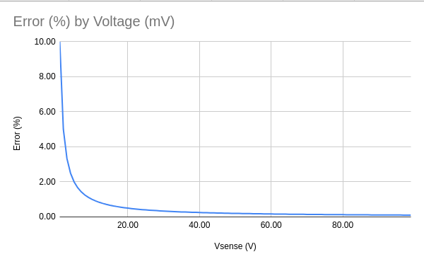
Error in this system will be measure of the measured output voltage of the amplifier compared to the ideal amplifier. There are numerous sources of error within a system but for this selection it's useful to focus on the amplifier's offset error. In an ideal amplifier when the difference between its inputs is zero the output will be zero, but amplifiers in the real world aren't ideal, and so there's a small amount of error that's added to the system called offset error. This error will be more prominent the smaller the measured voltage.
OffsetError = (Voffset / Vsense) * 100
VSense = Rshunt * Iload
OffsetError = (Voffset / (Rshunt * Iload)) * 100
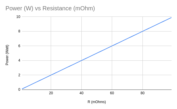
Power is defined as current multiplied by voltage (P = I * V), using ohms law we can substitute in the voltage drop across our resistor (Vsense) for V, and further I for Vsense / Rshunt (see above).
Power = Rshunt * (Iload ^ 2)
Lastly in order to read our values we want to fully saturate our available bandwidth of our measurement tools (for the ATtiny85 ADC that's 0 - VCC or in the case of my design 0-3V). The amplifier we choose will have some amount of gain, and based on that we can understand what values we can work with. Choosing the Texas Instruments INA 199 A1 as a reasonable example:
INA 199 A1
Gain = 50
Vout = 5
Voffset = 15mV

Max Resistance = (Vout / Gain)  / Maximum Current
Max Resistance = (3 / 50) / 100 = 0.60 mΩ
Using 500uΩ as our shunt resistance and putting it all together we get
Min Current = 30A
Max Current = 100A
Voffset = 150uV
Rshunt = 500uΩ

Error = Voffset / (Rshunt * Iload) * 100
Error = 15uV / (500uΩ * 30) * 100
Error = 1%

Power = Rshunt * (Iload ^ 2)
Power = 500uΩ * (100A ^ 2)
Power = 5W
Turns out the Mouser sells a 500uΩ, 5W shunt resistor at 1% precision. So I'll order that and see what I can do with it.
I put all of this together in a spreadsheet that folks are welcome to browse around.
- TI Products
- TI How to choose an appropriate shunt resistor
- INA199 26V current sense amplifier - Includes calculator for shunt size (
- Mouser shunt resistors
- Shunt Resistor Calculator
- TI Video Series on Shunt Resistors
- Four Terminal Sensing
- Digikey Summary of Current Sense Resistors
- Allegro 100A DC Current Sensor
- Input offset voltage